Quantcast
Channel: OpenFlows | Water Infrastructure
Viewing all 39611 articles
Browse latest View live

Forum Post: Re: Average velocity method

$
0
0

Is this a case where the inlets are sized for a 2 year storm and the pipes are sized for a 5 year storm? If so, using two scenarios works well. In the 5 year storm scenario, you just make sure that the inlets are set so they are not resized.

Regards,

Mal


Forum Post: Re: WaterCAD Saving Profile Line Thickness/Colour etc. ?

$
0
0

Hi Ben,

Thanks for your detailed post. Rest assured, we're aware of the concerns you raised. Regarding what you mentioned about the .wtg file; things are a bit more complicated than it may seem and there are some challenges to overcome in order to fully support persistence with chart options in profiles and system head curves. Enhancements in this area are currently being considered for the next major release.

Forum Post: Re: WaterCAD Nostalgia

$
0
0

I do still have the ruler since 2002 when I attend to Haestad Mehods course

Regards...................Mohamad

Forum Post: Re: Running Water Age Scenario in WaterGEMS, how to present in ArcMAP?

$
0
0

A third way I've had some success with is using ArcGIS to dump the data out instead of using WaterGems FlexTable "Export to File..." tool.

You can open the WaterGems model in ArcGIS, modify the GeoTable(s) to contain the fields you want, and use the Layer->Export Data ArcGIS tool to pump out to a standalone SHP, PGDB or FGDB feature class.

If it is an external GIS dataset you want to overwrite/update several times with modelling results, you can script a WaterGems ModelBuilder synchronisation definition (under the Tools Menu), that will automate further exports.

Forum Post: Re: PondPack ICPM

$
0
0

You should check the channel elevations against the elevation of the ponds they are connected to. If the pond top or bottom elevations are outside the range of channel elevations, then PondPack doesn't know what to do if the pond water surface reaches those elevations.

Regards,

Mal

Forum Post: Re: StormCAD - Culvert Headlosses in Open Channel System

$
0
0

Mal,

Thanks for the quick response.  Yes, I am currently interested in peak flow so I'm using StormCAD - will move to CivilStorm for hydrograph related analysis soon.  You say that the current version of StormCAD computes culvert headlosses . . .   I am using V8i, Select Series 2 (standalone and for Microstation) and have not seen this feature.  Am I missing something or is that a feature of Select Series 3?  Is there a way to model this type of headloss in the Series 2 application?

Forum Post: Re: SCS Initial Abstraction

$
0
0

I meant this is esp...ecially true for natural (undevelopped) watershed. I

Letting Ia = 0.2S, could mean you're underestimating runoff peak flow and volume for natural watershed.

For urban watershed, the S is usually low so, it doesn't affect much.

Hopefully there will be a way to change it in the future.

Thanks,

Forum Post: Re: StormCAD - Culvert Headlosses in Open Channel System

$
0
0

Thanks again, Mal . . .  You have confirmed my research into this yesterday.  I am checking our company's status with regards to upgrading to Select Series 3 and will use the standard headloss coefficient in the mean time.

Thanks for the advice.


Forum Post: Re: PondPack ICPM

Wiki Page: Modeling Force Mains With Air Valves [TN]

$
0
0

  
 Applies To 
  
 Product(s):Bentley SewerCAD
 Version(s):All V8 XM, V8i
 Environment: N/A
 Area: Modeling
 Subarea: N/A
 Original Author:Kristen Dietrich, Bentley Technical Support Group


Overview

The addition of the Air Valve element in SewerCAD V8 XM allows users to model forcemains with intermediate high points with greater ease and accuracy. This TechNote describes the effect of using air valves at high points in SewerCAD V8 XM, and also compares the implementation of the current capability with modeling approaches used in previous versions.

The Trouble with High Points

In previous versions of SewerCAD, the pump recognized a force main's outfall endpoint or manhole transition back to the gravity sewer piping as the boundary condition used to determine the pump's operating point and balance the energy equation. It did not account for raising the water over an intermediate high point.

Problems in the calculation frequently arose, therefore,  when an intermediate high point was present on the force main. The amount of head loss through the force main was sometimes significantly less than the difference in elevation between the pump station and the high point, which resulted in a negative pressures being calculated in the vicinity of the high point. This situation can be seen in the profile below, in which the hydraulic grade line (in blue) is lower than the pipe elevation at the high points.

This approach basically simulated the effect of water being siphoned over the high point, which is usually not the case in real systems, since most utilities place air release vacuum breaker valves at the high points, and since the vapor pressure of water limits the height of a potential siphon. Since neither of these factors was accounted for in most pressure pipe models, including older versions of SewerCAD, the results typically overestimated pump flow and underestimated head (i.e., the pump ran too far to the right on its curve).  

The modeling approach for this issue in earlier versions of SewerCAD was to place a manhole at the high point and put a "gravity" pipe in place of the force main on the downhill side of the high point. This worked well for systems where the downhill portion of the force main could flow by gravity for the entire range of modeled flows.

However, modelers sometimes found that, although the downstream portion of the force main flowed by gravity at lower flows, the force main functioned as a pressure pipe along its entire length for higher flows, as shown below. This situation could prove especially problematic in the case of an extended period simulation demonstrating both flow regimes.

Pressure flow

The Air Valve Solution

SewerCAD V8 XM provides an answer by incorporating a new air valve element. By placing an air valve at the high point, the pump sees the air valve elevation as its downstream boundary condition for instances in which pressure would have otherwise been negative at the high point.

Air Valve 

For instances in which the force main functions as a pressure pipe for its entire length (e.g., during the high-flow condition), the pump correctly sees the force main outfall or downstream manhole as the boundary, similar to the behavior in older versions.

When the air valve is open, the hydraulic grade on the downstream side may be less than the pipe elevation. This can be displayed as the hydraulic grade line drawn below the pipe. This should be interpreted as a pressure pipe that is not flowing full. Full flow resumes at the point where the hydraulic grade line crosses back above the pipe.


Because air valves have the possibility to switch status, they can lead to instability in the model especially if there are many air valves in the system. To improve the stability of the model, it is desirable to force some of the valves closed. This can be done by setting the property "Treat air valve as junction" to True for those valves that are expected to be closed anyway.

If all of the pumps upstream of an air valve are off, the pressure subnetwork is disconnected in that area and the model will issue warning messages for all nodes in that vicinity indicating that they are disconnected.

In addition, the profile between the air valve and the pumps that are Off will be inaccurate. To make the profile view accurate, you can place an imaginary wetwell on a short branch with a tiny diameter pipe at an Elevation (Initial) equal to the air valve elevation. This wetwell (which will not contribute significant flow) can eliminate the disconnected system message and correctly represent the fluid in the upstream pipe when the pump is off. Please note that the wetwell will need to be connected to the upstream side of the air valve. When the upstream pump is off, you may still see negative pressures downstream of the high point, which may be interpreted as part-full flow (the pipe may drain out). 


See Also

Product TechNotes and FAQs

Haestad Methods Product Tech Notes And FAQs 

External Links

Bentley Technical Support KnowledgeBase

Bentley LEARN Server


Wiki Page: Importing Loading Information Using Modelbuilder [TN]

$
0
0

  
 Applies To 
  
 Product(s):Bentley SewerCAD
 Version(s):08.11.00.48 and above
 Environment: N/A
 Area: Data Import/Export
 Subarea: N/A
 Original Author:Jesse Dringoli, Bentley Technical Support Group


Overview

This TechNote describes the process by which a user can import sanitary or inflow loading data using Modelbuilder. It assumes Bentley SewerCAD V8 XM will be used, but the process is the same for Bentley SewerGEMS V8i.

Background

In SewerCAD, loading information can be entered as a Hydrograph (flow vs. time), Unit based (unit type and count), Pattern based (base flow and pattern) or fixed load (single base flow, held constant.). Loads can be categorized as either sanitary dry weather or inflow wet weather.

If your loading data is in an Excel spreadsheet and you have a field that contains labels that match your SewerCAD model's manhole labels, you can use the Modelbuilder feature to import them. For example:


Note: if your loading information is contained within shapefiles, you will need to use the Loadbuilder tool to import them, based on the spatial information. This is outside the scope of this Technote.

If you attempt to import the loading information using Modelbuilder, you may end up with the following unexpected result:


As you can see, these pattern-based loads and Unit loads did not import correctly. The correct patterns/unit loads were not assigned and the load has imported as a Sanitary Hydrograph load type. Because of this, the base flow and unit count are ignored. There are two reasons why this has happened: 

  1. The patterns must be defined ahead of time, under Components > Patterns. Modelbuilder will not automatically create patterns; it is simply linking the data in your source file (the pattern labels) with the pattern field. If the patterns are not defined yet, then a matching selection will not be found and you will get the above warning. The same applies to the unit load label. Your unit load (for example, ‘Residential', representing 100 gpd per person) must also be defined ahead of time before the unit count can be imported into your manholes.
  2. Since a sanitary load can be a Hydrograph, Pattern-based, or Unit load, the user must specify which of these load types is being imported, in addition to the information already in the spreadsheet. Without specifying this Load Definition, the program will import the load as the default type, which is Sanitary Hydrograph.


Properly Importing your Loads in Modelbuilder


Note that when you import loads using this process, they will override any previous loads assigned to those manholes included in the spreadsheet. So, this process cannot be used to 'update' an individual load for manholes who have multiple items in the sanitary load collection. All of the loads that should be present for a particular manhole should be included in the spreadsheet when using this process.

First you must define your patterns (if importing any pattern-based loads). Go to Components > Patterns. Create a new hydraulic pattern and enter the starting multiplier along with the table of time and multiplier:


Ensure that the labels for your patterns match the ones in the source file that contains the loading data.


If you need to import any unit loads, you will then need to define them, under Components > Unit sanitary loads.


Next, open your source data file and add a new field called "Load Type". For each row of data, you will need to type in the corresponding load type. For sanitary loads, they must be entered exactly as follows (spelling and capitalization):

            Sanitary Unit Load
            Sanitary Pattern Load
            Sanitary Hydrograph

For manhole Inflow loads, they must match the following:

            Pattern
            Fixed Load
            Hydrograph Load

Your source file may look like this:


Note:Composite loads (more than one load per manhole) will also work. Meaning, you can have multiple rows with "MH-1", but with different loads. For example, MH-1 might have both a pattern load and a unit load, or perhaps it might have two different types of unit loads.


Next, start a new Modelbuilder run by going to Tools > Modelbuilder and clicking the white paper icon. Select your Data Source type and then the file itself. Click the check box next to only layer or worksheet that contains the data. You can click "Show Preview" to check the data in the layer selected:


Click Next. On the next page, uncheck all spatial/creation/deletion options. This is because we are updating elements, not creating or deleting them.

Click ‘Next' to display the field mappings. First, click on the layer on the left side and select "Manhole, Sanitary Loads" as the "Table" type.

Note that if you need to bring in one of the Inflow load types, you will need to select "Manhole, Inflow (Wet) Collection" as the table type. If you need to bring in a "Fixed Load" inflow load type, your source file will only need to include a column for the flow and for the load type (‘Fixed Load'.)


For the "Key/Label field", select the column name that contains the manhole labels. On the bottom of this window, each of your fields will be displayed. You will need to click each one and link them to the corresponding SewerCAD field.

‘Base Flow' - the base flow field associated with a pattern-based load (Make sure you check your units!)
‘Index' - This is used for hydrograph loads (beyond the scope of this TechNote)
‘Load Definition (ID)' - the internal ID number of the load type. This does not need to be used.
‘Load Definition (Label)' - the field containing the type of sanitary load you are importing (described above)
‘Loading Unit Count' - the count field associated with a unit load
‘Pattern (ID)' - the internal ID number of a pattern. This does not need to be used.
‘Pattern (Label) - the field containing the name of the pattern associated with a pattern-based load
‘Unit Sanitary Load (ID)' - the internal ID number of the unit load. This does not need to be used.
‘Unit Sanitary Load (Label)' - the field containing the name of the unit load for a unit sanitary load.

Note: not every one of these fields will necessarily be used. For example, if you are only importing pattern loads, you would only need to link the "Pattern (Label)" and "Base Flow" fields.

Once completed, your window will look similar to this:


Note that if you need to import a hydrograph load, the process is different and outside the scope of this TechNote. The table of flow vs. time needs to be imported first, using the hydrograph table type. The load would then need to be assigned to the manhole using the index in the sanitary or inflow collection table type.


Click Next and choose to build the model. Check the "Messages" tab for any warnings and then close Modelbuilder. Open the Sanitary Load Control Center. The loads should have been imported correctly.

Note that the loads/inflow that you import using Modelbuilder will be imported into the scenario that is active before opening Modelbuilder. This means that the loading/inflow data is imported into the "Sanitary Loading" or "Inflow" alternative assigned to that scenario.


For a pattern based load, if the pattern is "fixed", you'll get a warning at the end of the Modelbuilder run that the Fixed load could not be found. This message can be ignored, but if you have a lot of fixed loads and you're doing a steady state analysis, you may want to consider importing them as Fixed inflows instead. This is a special type of load that falls under the "Inflow category". This involves only a single value, so you don't have to associate it with a pattern.


See Also

Product TechNotes and FAQs

Haestad Methods Product Tech Notes And FAQs

Water and Wastewater Forum

External Links

Bentley homepage

Bentley Technical Support KnowledgeBase

Bentley LEARN Server

Wiki Page: Compatibility Chart [TN]

$
0
0

  
 Applies To 
  
 Product(s):WaterCAD, WaterGEMS, PondPack, StormCAD, SewerCAD, FlowMaster, CulvertMaster, Hammer, SewerGEMS, CivilStorm
 Version(s):Last four versions
 Environment: N/A
 Area: General
 Subarea: N/A
 Original Author:Shahzaib Bukhari, Bentley Technical Support Group


Compatibility Chart


WaterCAD & WaterGEMS XM& V8i

Version

08.11.04.50 (ss4)

08.11.03.16/17/19 (ss3)

08.11.02.31 (ss2)

08.11.01.32 (ss1)

Date Released

5/6/2013

 7/8/2011

11/24/2010

10/26/2009

O/S compatibility

Windows XP SP3 (32 bit) Windows 7 (32 bit/64 bit)

Windows Server 2003 (SP2 or later, 32 bit/64 bit)

Windows Vista (SP2, 32 bit/64 bit)

Windows 2008 Server (32 bit/64 bit)

Windows 2008 Server R2 (64 bit only)

Windows XP SP3 (32 bit) Windows 7 (32 bit/64 bit)

Windows Server 2003 (SP2 or later, 32 bit/64 bit)

Windows Vista (SP2, 32 bit/64 bit)

Windows 2008 Server (32 bit/64 bit)

Windows 2008 Server R2 (64 bit only)

Win XP SP3, Win 7
WinXP (SP2 or later)WinXP 64-bit (SP2 or later)Win Server 2003 (SP2 or later)Win Vista, Win2008 Server (32 bit/64 bit)Win2008 Server R2 (64 bit only)

XPSP3, VistaSP2, XPSP1/2*, XP64*, VistaSp0*, W2008*, Win7*

Supported AutoCAD Versions ( * = basic testing only)

AutoCAD 2012 and 2013 (32-bit and 64-bit

2012 (32-bit & 64-bit), 2011 (32-bit), 2011 (64-bit)*

2011, 2010*

 2010, 2009*

MicroStation integration

 08.11.09.xx (SS3)

 08.11.07.xx (ss2)

8.11.7.443 (SS2)

08.11.09.xx (SS3) 

8.11.7.443 (SS2) 

 8.11.7.x

ArcGIS versions in WTRG & WTRC

 ArcGIS 10 SP5 and 10.1 (SP1)

9.3.1 SP2, 10 (Certified in 10 only)

 9.3, 10

9.3, 9.3 Service pack 1

Version of .NET needed

 3.5 SP1

3.5 SP1

3.5 SP1

3.5 + SP1


PondPack v10& Pondpack V8i compatibility chart

Version

08.11.01.56

08.11.01.54

08.11.01.51

10.01.04.00

Date Released

3/8/2012

12/16/2010

10/26/2009

11/7/2008 

O/S compatibility

Windows XP SP3 (32 bit)Windows 7 (32 bit/64 bitWindows Server 2003 (SP2 or later, 32 bit/64 bit)Windows Vista (SP2, 32 bit/64 bit)Windows 2008 Server (32 bit/64 bit)Windows 2008 Server R2 (64 bit only)

Win XP SP3, Win 7
WinXP (SP2 or later)WinXP 64-bit (SP2 or later)Win Server 2003 (SP2 or later)Win Vista, Win2008 Server (32 bit/64 bit)Win2008 Server R2 (64 bit only)

XP SP3 (32/64), Vista SP2, XP (SP2 or later)*, XP 64-bit (SP2 or later)*, s2003 (SP2 or later)*, s2008*, Windows 7 (32 & 64 bit)*, s2008 R2*


 XP SP1-SP3 (32 and 64 bit), Vista SP 1 32bit, Vista 64bit*, Server 2003 (32 and 64 bit)*

Supported AutoCAD Versions ( * = basic testing only)

2011 (32 bit)*

2012 (32 bit)*

2011, 2010

2010, 2009*

N/A

MicroStation integration

8.11.7.x and 8.11.9.x

8.5.xx.xx /8.11.7.xx

8.11.5.x

N/A

ArcGIS versions in Pondpack

N/A

N/A


N/A

N/A

Version of .NET needed

3.5 + SP1

3.5 + SP1

3.5 + SP1 

1.1


StormCAD V8 XM& StormCAD  V8i  SS1 compatibility chart

Version

 08.11.03.77(ss3)

08.11.02.75(ss2)

08.11.02.38(ss2)

 08.11.02.35(ss2)

Date Released

 1/7/2013

11/7/2011

12/16/2010

 05/05/2010

O/S compatibility

- Windows XP SP3 (32 bit)
- Windows 7 (32 bit/64 bit)
- Windows Server 2003 (SP2 or later, 32 bit/64 bit)
- Windows Vista (SP2, 32 bit/64 bit)
- Windows 2008 Server (32 bit/64 bit)
- Windows 2008 Server R2 (64 bit only)

-Windows 8

-Windows 8 x 64

- Windows XP SP3 (32 bit) - Windows 7 (32 bit/64 bit)- Windows Server 2003 (SP2 or later, 32 bit/64 bit Windows Vista (SP2, 32 bit/64 bit)- Windows 2008 Server (32 bit/64 bit)- Windows 2008 Server R2 (64 bit only)

 Vista SP2, XP SP3, Windows 7, XP (SP2 or later)*, XP 64-bit (SP2 or later)*, s2003 (SP2 or later)*, Vista, s2008 (32 bit/64 bit)*, s2008 R2 (64 bit only)*

 Vista SP2, XP SP3, Windows 7, XP (SP2 or later)*, XP 64-bit (SP2 or later)*, s2003 (SP2 or later)*, Vista, s2008 (32 bit/64 bit)*, s2008 R2 (64 bit only)*

Supported AutoCAD Versions ( * = basic testing only)

2012 (32-bit & 64-bit)2013 (32-bit & 64-bit)

 2012 (32-bit & 64-bit), 2011 (32-bit), 2011 (64-bit)*

2011, 2010, 2009*
 

 2010, 2009*

MicroStation integration

08.11.7.443(ss2), 08.11.09.357 (ss3)

 8.11.7.443 and 8.11.9.209 (beta)

8.11.5, 8.11.7

8.11.5, 8.11.7

Version of .NET needed

3.5 SP1

3.5 + SP1

3.5 + SP1

3.5


SewerCAD V8 XM& SewerCAD  V8i compatibility chart

Version

08.11.02.75 

 08.11.02.49 (ss2)

 08.11.02.46 ss2)

08.11.00.52

Date Released

 11/7/2011

 12/16/2010

 07/01/2010

 11/6/2008

O/S compatibility

- Windows XP SP3 (32 bit)
- Windows 7 (32 bit/64 bit)
- Windows Server 2003 (SP2 or later, 32 bit/64 bit)
- Windows Vista (SP2, 32 bit/64 bit)
- Windows 2008 Server (32 bit/64 bit)
- Windows 2008 Server R2 (64 bit only)

 XP SP3, Vista SP2 (32/64), Windows 7 (32/64), s2003 SP2 (32/64)*, Vista SP0/SP1 (32/64)*, s2008 SP1/SP2 (32/64)*, s2008 R2 (64 only)*

XP SP3, Vista SP2 (32/64), Windows 7 (32/64), s2003 SP2 (32/64)*, Vista SP0/SP1 (32/64)*, s2008 SP1/SP2 (32/64)*, s2008 R2 (64 only)*

XP, Vista, XP64*, Vista64*,s2003*, s2003-64*, s2008*, s2008-64*

Supported AutoCAD Versions ( * = basic testing only)

2012 (32-bit & 64-bit), 2011 (32-bit), 2011 (64-bit)*

2010, 2011

 2010, 2011

 2009, 2008*

MicroStation integration

08.11.7.443(ss2), 08.11.09.357 (ss3

08.11.7.x

 8.11.7.x

 8.11.5.x

Version of .NET needed

 3.5 SP1

 3.5 SP1

 3.5 SP1

 3.5


FlowMaster compatibility chart

Version

08.11.01.03

08.11.00.03

08.01.071.00

08.01.068

Date Released

11/14/2009

8/27/2008

3/6/2007

11/10/2006

O/S compatibility

XP SP3, Vista SP2 (32/64), Windows 7 (32/64), s2003 SP2 (32/64)*, Vista SP0/SP1 (32/64)*, s2008 SP1/SP2 (32/64)*, s2008 R2 (64 only)*


s2003*, s2003-64*, XP, XP64*, Vista, Vista64* Win 7 is now supported

Win 2000, S2003, XP, XP64, Vista, Vista64

Win 2000/XP (32/64bit)

Version of .NET needed

2.0

2.0

1.1

1.1


CulvertMaster compatibility chart

Version

03.03.00.04

03.02.00.01

03.01.010.00

03.01.009.00

Date Released

11/5/2009

8/11/2008

2/14/2007

12/6/2005

O/S compatibility

Vista SP2, XP SP3 (32/64), XP (SP2 & up), XP 64-bit (SP2    & up), s2003 (SP2 & up), s2008, Windows 7, s2008 R2

s2003*, s2003-64*, XP, XP64*, Vista, Vista64*

Win 2000, s2003, XP, XP64, Vista, Vista64

Win 2000/XP (32/64bit)

Version of .NET needed

2.0

2.0

2.0

1.1


Hammer XM& Hammer V8i compatibility chart

Version

08.11.04.50 (ss3)

08.11.03.16/17/19

08.11.02.31 

08.11.01.32 

Date Released

5/6/2013

7/8/2011

12/7/2010

10/26/2009

O/S compatibility

Windows XP SP3 (32 bit) Windows 7 (32 bit/64 bit)

Windows Server 2003 (SP2 or later, 32 bit/64 bit)

Windows Vista (SP2, 32 bit/64 bit)

Windows 2008 Server (32 bit/64 bit)

Windows 2008 Server R2 (64 bit only)

Windows XP SP3 (32 bit)
Windows 7 (32 bit/64 bit)
Windows Server 2003 (SP2 or later, 32 bit/64 bit)
Windows Vista (SP2, 32 bit/64 bit)
Windows 2008 Server (32 bit/64 bit)
Windows 2008 Server R2 (64 bit only)

Win XP SP3, Win 7
WinXP (SP2 or later)WinXP 64-bit (SP2 or later)Win Server 2003 (SP2 or later)Win Vista, Win2008 Server (32 bit/64 bit)Win2008 Server R2 (64 bit only)

XPSP3, VistaSP2, XPSP1/2*, XP64*, VistaSp0*, W2008*, Win7*

Supported AutoCAD Versions ( * = basic testing only)

AutoCAD 2012 and 2013 (32-bit and 64-bit

2012 (32-bit & 64-bit), 2011 (32-bit), 2011 (64-bit)*

2011, 2010*

2010, 2009*

ArcGIS versions in Hammer

ArcGIS 10 SP5 and 10.1 (SP1)

9.3.1 SP2, 10 (Certified in 10 only)

9.3.1 SP1, 10

9.3, 9.3 service pack 1

MicroStation integration

 08.11.09.xx (SS3)

 08.11.07.xx (ss2)

8.11.7.443

8.11.7.443

8.11.7.x

Version of .NET needed

3.5 SP1

3.5 SP1

3.5 + SP1

3.5 +SP1


SewerGEMS V8 XM& SewerGEMS V8i compatibility chart

Version

08.11.03.77 (ss3)

08.11.02.75 (ss2)

08.11.02.49(ss2)

08.11.02.46(ss2)

Date Released

12/19/2012

11/7/2011

12/16/2010

 07/01/2010

O/S compatibility

- Windows XP SP3 (32 bit)
- Windows 7 (32 bit/64 bit)
- Windows Server 2003 (SP2 or later, 32 bit/64 bit)
- Windows Vista (SP2, 32 bit/64 bit)
- Windows 2008 Server (32 bit/64 bit)
- Windows 2008 Server R2 (64 bit only)

-Windows 8

-Windows 8 x 64

- Windows XP SP3 (32 bit)
- Windows 7 (32 bit/64 bit)
- Windows Server 2003 (SP2 or later, 32 bit/64 bit)
- Windows Vista (SP2, 32 bit/64 bit)
- Windows 2008 Server (32 bit/64 bit)
- Windows 2008 Server R2 (64 bit only)

Win XP SP3, Win 7
WinXP (SP2 or later)WinXP 64-bit (SP2 or later)Win Server 2003 (SP2 or later)Win Vista, Win2008 Server (32 bit/64 bit)Win2008 Server R2 (64 bit only)

XP SP3, Vista SP2 (32/64), Windows 7 (32/64), s2003 SP2 (32/64)*, Vista SP0/SP1 (32/64)*, sServer SP1/SP2 (32/64)*, s2008 R2 (64 only)*

Supported AutoCAD Versions ( * = basic testing only)

2012 (32-bit & 64-bit)

2013 (32-bit & 64-bit)

2012 (32-bit & 64-bit), 2011 (32-bit), 2011 (64-bit)*

2010, 2011

  2010, 2011

ArcGIS versions in SWRG

10 or 10.1

9.3.1 SP2 + ArcGIS 10

9.3.x

9.3.x

MicroStation integration

08.11.7.443(ss2), 08.11.09.357 (ss3

8.11.7.X, 8.11.9.209 (beta)

08.11.7.x 

08.11.7.x

Version of .NET needed

3.5 SP1

3.5 SP1

3.5 SP1

3.5 SP1


CivilStorm V8 XM& CivilStorm V8i compatibility chart

Version

08.11.03.77(ss3)

08.11.02.75(ss2)

08.11.02.65 (ss2)           

08.11.02.62 (ss2)  

Date Released

1/17/2013

11/7/2011

 12/16/2010 

 8/27/2010

O/S compatibility

- Windows XP SP3 (32 bit)
- Windows 7 (32 bit/64 bit)
- Windows Server 2003 (SP2 or later, 32 bit/64 bit)
- Windows Vista (SP2, 32 bit/64 bit)
- Windows 2008 Server (32 bit/64 bit)
- Windows 2008 Server R2 (64 bit only)

-Windows 8

-Windows 8 x 64


- Windows XP SP3 (32 bit)
- Windows 7 (32 bit/64 bit)
- Windows Server 2003 (SP2 or later, 32 bit/64 bit)
- Windows Vista (SP2, 32 bit/64 bit)
- Windows 2008 Server (32 bit/64 bit)
- Windows 2008 Server R2 (64 bit only)

Win XP SP3, Win 7
WinXP (SP2 or later)WinXP 64-bit (SP2 or later)Win Server 2003 (SP2 or later)Win Vista, Win2008 Server (32 bit/64 bit)Win2008 Server R2 (64 bit only)

Win XP SP3, Win 7
WinXP (SP2 or later)WinXP 64-bit (SP2 or later)Win Server 2003 (SP2 or later)Win Vista, Win2008 Server (32 bit/64 bit)Win2008 Server R2 (64 bit only)Win XP SP3, Win 7
WinXP (SP2 or later)WinXP 64-bit (SP2 or later)Win Server 2003 (SP2 or later)Win Vista, Win2008 Server (32 bit/64 bit)Win2008 Server R2 (64 bit only)

Supported AutoCAD Versions ( * = basic testing only)

2012 (32-bit & 64-bit)2013 (32-bit & 64-bit)

2012 (32-bit & 64-bit), 2011 (32-bit), 2011 (64-bit)*

2011, 2010

2011, 2010

ArcGIS IntegrationN/A N/AN/A N/A

Microstation integration

08.11.7.443(ss2), 08.11.09.357 (ss3

8.11.7, 8.11.9.209 (beta)

8.11.7.X

8.11.7.X

Version of .NET needed

 3.5 SP1

3.5 SP1 

3.5 SP1

3.5 SP1


Wiki: Hydraulics and Hydrology Wiki

Forum Post: Re: WATEROBJECT.NET : JUNCTION COLORING

$
0
0

Hello Akshaya,

thanks for your response.

I want to develop an application with (C# - WaterObjects.NET) where you can change the colors of the junctions  and then view the network modified (with the colors of the joints changed)  with WaterGEMS.....so is this possible manipulating the .mdb model of the Hydraulic net?

thanks again

giancarlo

Forum Post: Re: Using Common FlexTables for Various Users and Projects

$
0
0

Project-level FlexTables are available only for the project in which you create them.  The Shared FlexTables are available for all projects for the user that created them and are stored in the user's profile.  If you create shared FlexTables, they will be in each project that you create or edit.

There is not a way to import FlexTables.  If you want all users to use the same FlexTables, you can copy the FlexTables.xml file to a network folder, or send it to each user.  If it is in a network folder, each user would need to copy it to their user profile folder (C:\Users\<username>\AppData\Local\Bentley\PondPack\8 on a Windows 7 computer).  However, if any one person updates the .xml file, it will need to be redistributed to all users.


Forum Post: Runoff Volume at a node

$
0
0

I would like to see what is the total runoff volume (m3) at a particular node (outlet or manhole) and I can't seem to find it under the report file.

Where should I look? 

Forum Post: Re: WATEROBJECT.NET : JUNCTION COLORING

$
0
0

Hi Mr Walski,

i'm trying to display a district metering computation.

My idea is to associate for every junction a different zone based the district metering computation. (in the physical properties of  the junction there is the item "zone") .

Then from  Watergems i can associate  (by hand) the color of the junction with a different zone.......so it would be possibile to visualize a district metering computation...........in a "user friendly manner"......

Any suggestion will be apprectiated

thanks

giancarlo  

Forum Post: Re: WATEROBJECT.NET : JUNCTION COLORING

$
0
0

Hi Giancarlo,

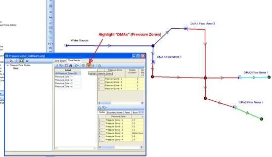
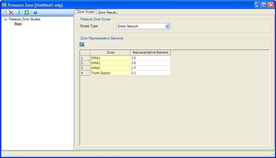
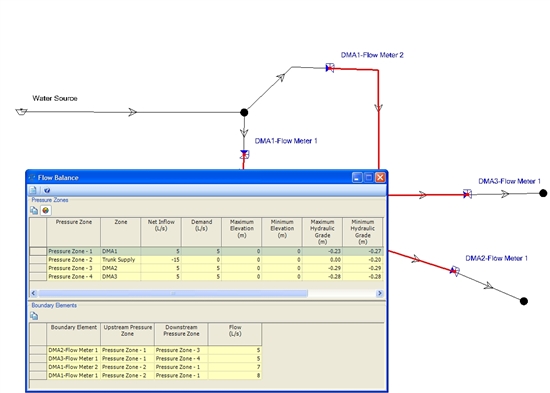
You might find much of this functionality already in WaterCAD's/WaterGems's Pressure Zone Manager.  This has the ability (with some tweaks) to automatically derive and color-code DMAs, as well as calculate the DMA flow balance.

Highlighting "District Metered Areas"

Associating Pressure Zones to DMA "Zones"

Using the Flow Balance Tool

Forum Post: Re: Runoff Volume at a node

$
0
0

If you're referring to SewerGEMS or CivilStorm, you can use the Hydraulic Reviewer (under the Tools menu) to see the total volume of inflow, outflow and overflow for nodes.

Blog Post: New Edition of "Computer Applications in Hydraulic Engineering" Book Now Available

$
0
0

Computer Applications in Hydraulic Engineering, 8th Edition

Dr. Tom Walski (Author), Tom Barnard (Author), Rocky Durrans (Author),
Mike Meadows (Author), Steve Lowry (Author), Brian Whitman (Author)
ISBN: 9781934493168

Bentley Institute Press’s all-time best-selling textbook returns with a
fully updated eighth edition!

Computer Applications in Hydraulic Engineering (CAiHE), 8th Edition is an all-inclusive water resources guide for practicing engineers and students in the hydraulics and hydrology fields. It links theory with real-world applications through exercises and examples of the technology, theory, and analysis methods at the forefront of hydraulic engineering. The examples cover everything from water quality analysis and hydraulic theory to detention pond design, dynamic modeling, culvert hydraulics, and more.

The book includes an accompanying DVD with academic licenses of the flagship products in Bentley’s water and wastewater solution, as well as updated and expanded tutorials that reflect the software’s latest advances. Also new to the 8th edition is a chapter about transient analysis that features step-by-step tutorials that demonstrate how to identify, manage, and mitigate transient risks using Bentley HAMMER.

Software included:

  • WaterGEMS
  • SewerGEMS
  • SewerCAD
  • StormCAD
  • CulvertMaster
  • FlowMaster
  • HAMMER
  • PondPack

Meet the Authors:

The contributing staff is a diverse group of professionals with experience ranging from software development and engineering consulting to public works and academia. Led by Dr. Tom Walski, the authors that contributed to Computer Applications in Hydrualic Engineering, 8th Edition include Tom Barnard, Rocky Durrans, Mike Meadows, Steve Lowry, and Brian Whitman. This broad cross section of expertise contributes to the development of some of the most comprehensive software and educational materials in the civil engineering industry.

Read an excerpt of Computer Applications in Hydraulic Engineering, 8th Edition or order the book online today!

Standard Edition: $295 | Academic Edition: $80
(Prices in U.S. Dollars)

Or call the order desk:

1-800-225-2613  United States and Canada
1-610-321-6476 Worldwide


http://www.bentley.com/en-US/Training/Products/Resources/Books/CAiHE+8th+edition.htm

Viewing all 39611 articles
Browse latest View live


<script src="https://jsc.adskeeper.com/r/s/rssing.com.1596347.js" async> </script>